Design Summary
Shape
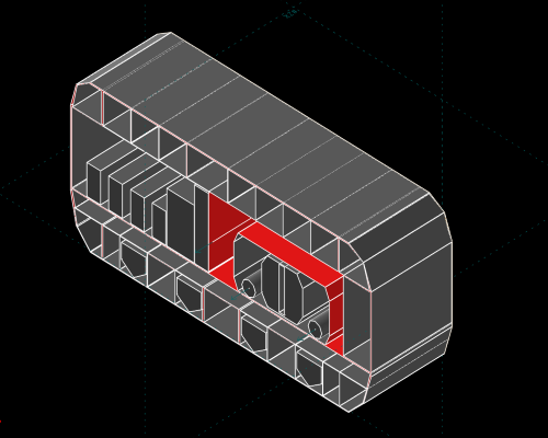
by blackswift.space / Design / 1The design of the Landers was inspired by the 60's VW microbus, with a rectangular shape seen as an optimal use of available space for a vehicle. The Landers come in static and mobile versions, as well as robotic ones.
Back to Top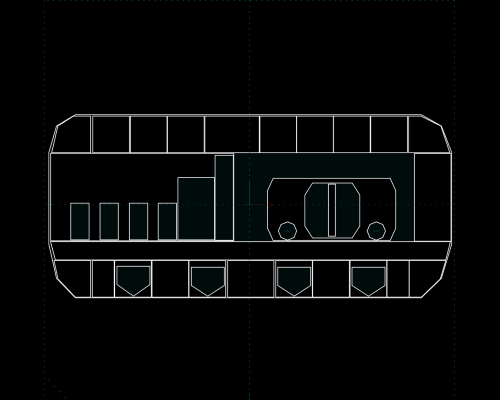
Structure
by blackswift.space / Design / 2The Landers's structure varies in length and diameter, and is made of 5 decks, the robotic versions of 3 decks. The structure is made mostly of Titanium or Aluminium alloy, consisting of beams, bulk-heads and tessellated spans.
Back to Top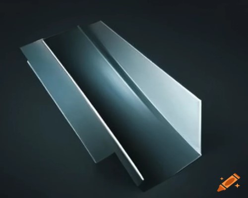
Aeroshell
by blackswift.space / Design / 16Their aeroshell is made of Boron carbide (B4C) covered Titanium panels. The front and bottom of the Landers, have thicker layers of B4C and Carbon foam. Some versions have Kevlar and Kapton added to their exterior.
Back to Top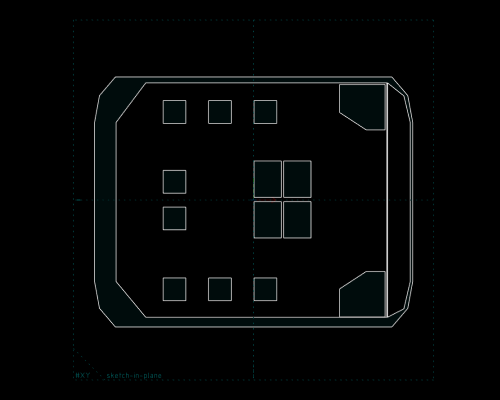
Cockpit
by blackswift.space / Design / 3The 5+M cockpit has enough space for 6 to 8 astronauts. There are also 2 lavatories, and 2 or 4 storage spaces. Docking is in the top center of the cockpit. Control panels are liquid-proof, and OLED screens replace cockpit windows.
Back to Top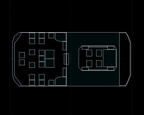
Cargo Bay
by blackswift.space / Design / 3The cargo bay is 6M in length, and can handle several metric tons of cargo. It is large enough for a moon buggy 3.5M in length and 2.5M in width. It has 2.5 meter cube of upper cabinet storage space, and 8 additional seats can unfold from the wall.
Back to Top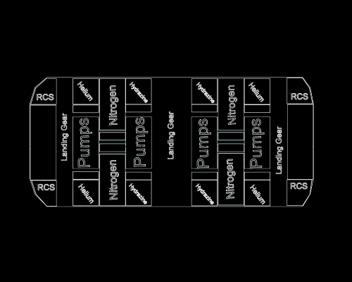
Lower Deck
by blackswift.space / Design / 4The lower decks have enough space to accommodate the main fuel tanks, along with the aerospikes and landing supports. The landing supports are either static or powered legs, or wheels. Legs have cupolas or seabirds palmed-feet made of Titanium.
Back to Top
Mid Deck
by blackswift.space / Design / 5Space required for cockpit and cargo bay is located in the mid deck, in the non-robotic versions. The sub-layer of the mid-deck is where all the main fuel pumps are located, alongside Nitrogen, Hydrazine, Halon and Helium tanks, cryo-coolers, and heaters.
Back to Top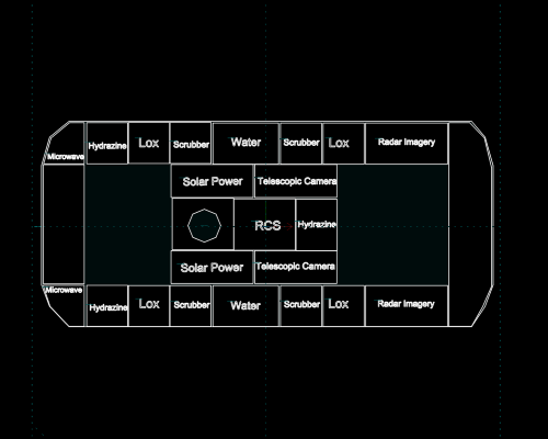
Upper deck
by blackswift.space / Design / 7Water tanks, scrubbers, electrical power generators, etc. are housed in the upper deck. A microwave and LASER dish are used for communication links. A live feed, of the entire trip, could be relayed back to Earth using a 100+ Mbps bandwidth.
Back to Top
Foam & Coatings
by blackswift.space / Design / 5The fuselage, battery casings, electrical conduits, and aerospikes are filled with silica or carbon foam or aerogel, which are also used for sound and thermal proofing. Memory shape foam is used for furniture, and seat paddings.
Back to Top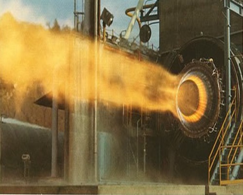
Propulsion
by blackswift.space / Design / 4Propulsion is provided by a set of toroidal aerospikes. They each fit within a one meter or less than half a meter square box, in the Landers's bottom deck. The minimal set is 4 on the Lander 7M, 8 for the Lander 12M, and 4 for the 2-meter robotic versions.
Back to Top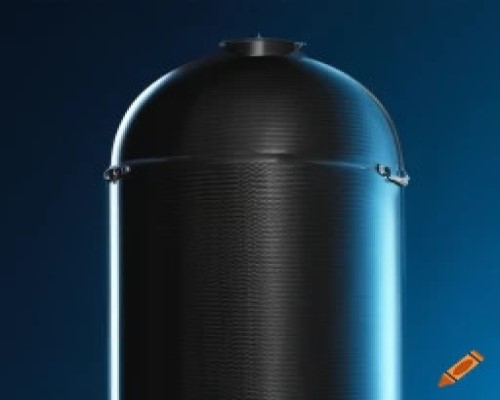
Fuel Tanks
by blackswift.space / Design / 8Propellant is Ethanol and Liquid Hydrogen (LH2) with Liquid Oxygen (LOX) or Nitrous Oxide (N2O). The LH2 and LOX tanks are made of Carbon fiber, or Titanium. The Ethanol and possibly the N2O tanks are built as integral parts of the fuselage.
Back to Top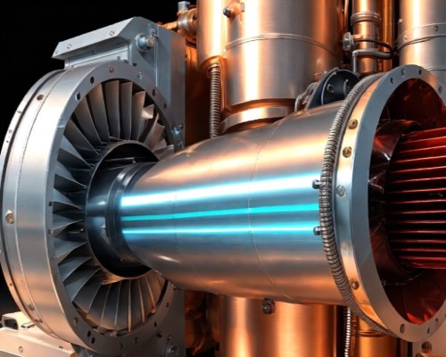
Power
by blackswift.space / Design / 8Power is provided by a pair of solar concentrators on top of the Lander. A set of Hydrogen fuel-cell packs are used for backup power in case of emergency. The Blackswift PPMs©® power generators are also planned for use in the Landers.
Back to Top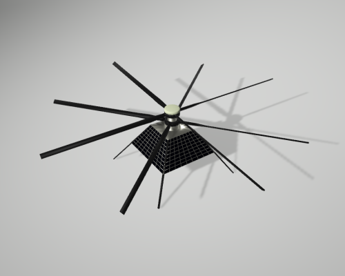
Mars Helo
by blackswift.space / Design / 7The design aim of the Mars Helo© was to reduce complexity and weight for an helicopter built to fly on Mars at a barometric pressure found on Earth at an altitude of 34 kilometers.
A microwave and/or LASER dish are used for a Line of Sight (LoS) communication link with the Mars lander or robotic rover.
Three 120 degrees digital cameras, located in the bottom pod delivers 2k or 4K panoramic scene to the Mars lander or robotic rover. The Helo's flight path is a circular one of 314.159 meters with one 4K panoramic snapshot per second, at an altitude of 15 to 30 meters.
Back to Top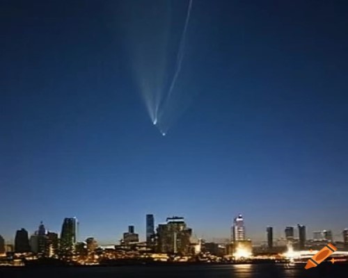
Re-Entry
by blackswift.space / Design / 7The Lander uses head-first Dragon Lizard atmospheric entry with an expandable set of heat shield spoilers, and parachutes. Belly flopping with HyperGlide™©® is used by other landers; and as an alternate choice for The Lander.
After the atmospheric entry heat phase, circular gliding trajectory is followed until subsonic speed is reached, to be able to right the Lander for vertical landing with thrusters or/and parachutes.
Landers are designed for both atmospheric and non atmospheric entry. They can land on the Moon, Mars, and Earth. They can achieve delta-v on the Moon and Mars.
Back to Top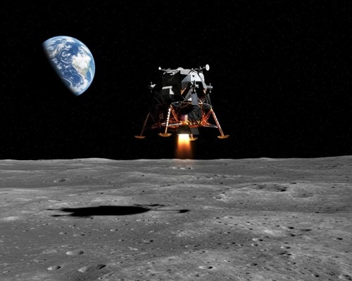
Landing
by blackswift.space / Design / 7The Lander uses a 3-phase landing descent trajectory, with the first phase being a 30 to 60 second burn to decelerate to subsonic speed, the second phase is a shorter duration burn to slow or stop the Lander's forward momentum, which then allows for the third phase consisting of stopping the Lander's forward motion; and then, a slow drop over the landing zone, and enough of a margin, time-wise, to select alternate landing spots if the original is no longer appropriate.
To ensure a safe landing, both Radar and Lidar ranging are used, with a deployable tether as a last resort distance measurement device.
Back to TopInvestors welcome !
For more information